Indirect refrigeration design for cold storage: the fluid decisions
Cold storage loops are built around indirect secondary cooling. See how fluid choice, concentration and temperature drive pump sizing, materials and running cost.
THE SHORT ANSWER
What you need to know.
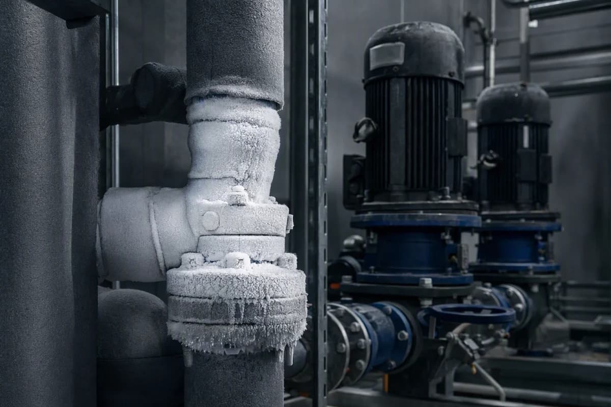
An indirect cold storage system moves heat from the rooms to the plant through a secondary coolant rather than circulating the primary refrigerant around the building. The design consequences follow from that choice: the fluid's viscosity at the lowest operating temperature sets pump duty, its concentration sets the freezing margin, and its materials list sets which pipework, seals and coils are acceptable. Get the lowest evaporating temperature and the required flow rate established first, because those two numbers constrain everything else.
- Indirect cooling reduces primary refrigerant charge and moves the hazard to the plant room, but adds a pump and a secondary fluid to the design.
- Pump duty follows the coolant's viscosity at the coldest condition, not at ambient — low-temperature viscosity is a design input, not a datasheet footnote.
- The wetted-material list and the concentration target belong in the specification before equipment is ordered.
Why cold stores are usually indirect
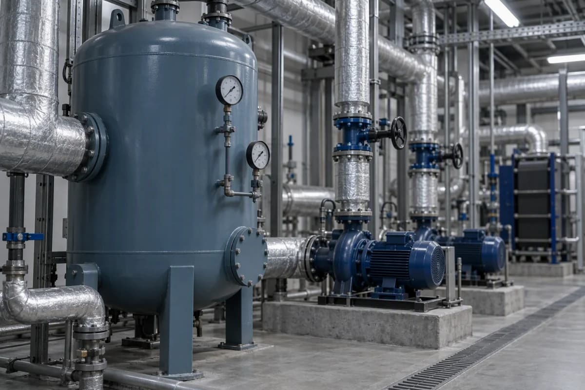
A cold storage facility built thirty years ago probably circulated its primary refrigerant straight to the evaporators in each room. Most new designs do something different: they keep the refrigerant in a plant room, run a chiller or a pumped vessel, and move heat around the building with a secondary coolant.
The shift is not fashion. It is downstream of two pressures.
The first is charge. Refrigerants such as ammonia are efficient and cheap, and they are also hazardous, which means the size of a permitted charge and the number of occupied spaces it may pass through are regulated. Confining the charge to a plant room and serving the rooms through a secondary loop changes that calculus entirely. The second pressure is control. A single plant can run at one evaporating temperature while separate secondary circuits hold different rooms at different temperatures through three-way mixing, which is often easier than building multiple primary circuits.
The trade is a heat-exchange temperature step, a pump set, and a fluid that has to be specified and maintained. That fluid is where a surprising number of design decisions accumulate.
Start with two numbers, not with a fluid
The temptation is to choose a coolant early. The more productive order is to establish two quantities first, because they constrain everything after.
The lowest evaporating or supply temperature the loop will reach. Not the room temperature — the temperature the coolant must be at when it leaves the chiller or vessel serving the coldest room. Include pull-down and defrost conditions, not just steady state.
The required flow rate. This comes from the cooling load and the permitted temperature rise across the load. Note that designing for a smaller temperature rise increases flow, which increases pump duty — a real cost that shows up in the operating budget rather than the capital budget.
Those two numbers, applied to the candidate fluids, produce the third number that governs the design: viscosity at the coldest condition. Pump and pipe sizing follow from it, not from a room-temperature figure.
Viscosity at the cold end is the design driver
This is the single most commonly underweighted input in an indirect cold storage design.
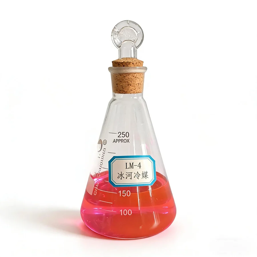
Low-temperature coolants do not differ dramatically in volumetric heat capacity, but their viscosity can differ by an order of magnitude, and viscosity is what drives pressure drop. The concentration tables show this clearly. In the LM-4 series, the freezing point improves steadily with concentration — but the viscosity at the corresponding low temperature rises steeply:
| Concentration (wt%) | Freezing point | Viscosity (measured at) |
|---|---|---|
| 20 | −8 °C | 2.45 cP at 5 °C |
| 30 | −15 °C | 5.49 cP at −5 °C |
| 40 | −23 °C | 12.37 cP at −15 °C |
| 50 | −35 °C | 32.90 cP at −25 °C |
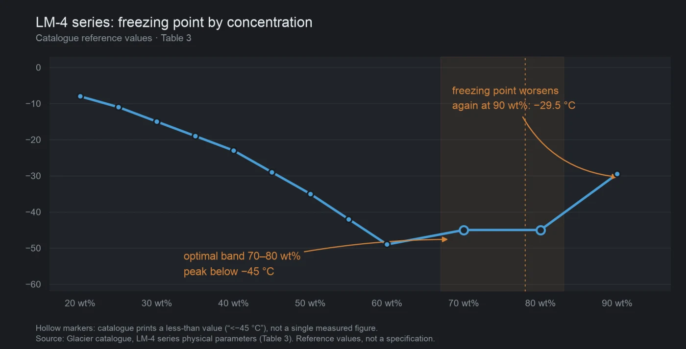
Reading across that table, the concentration that buys the freezing margin you need also sets the pump duty you have to pay for — note that the viscosity figures are measured at progressively colder temperatures, so the column reflects both effects. There is no free direction, and past the optimum the freezing point itself turns back: the figures give a sub-−45 °C value at 80 wt% and −29.5 °C at 90 wt%. The trade-off is analysed in why pumping energy decides a low-temperature coolant, and the concentration mechanics are set out in how much glycol to add.
Where the chemistries separate
Three families are commonly shortlisted for cold storage work, and they separate on more than price.
Glycol-type and diol coolants. Dilutable, so the user sets the concentration and therefore the operating window. Well suited to medium-temperature storage and to systems where a single fluid serves several duties. Their limitation is the viscosity rise at the cold end.
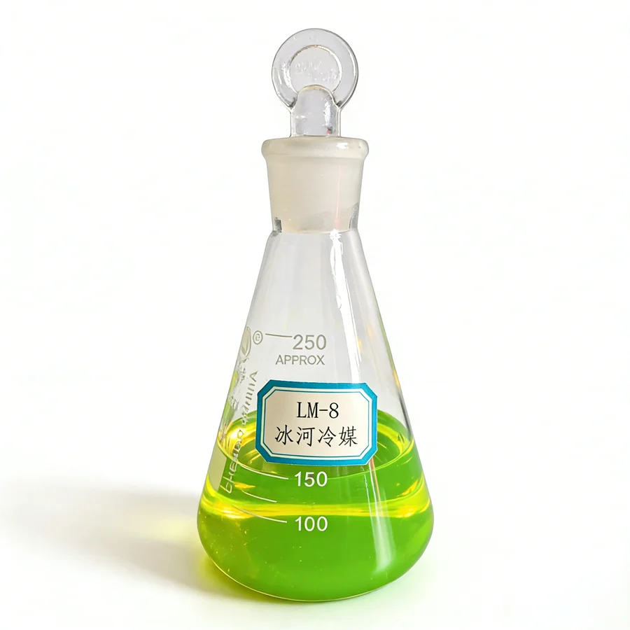
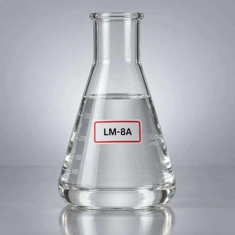
Salt-based secondary refrigerants. LM-8A is the inorganic salt secondary refrigerant, and the LM-8 series covers modified organic acid salts with low-temperature variants. These carry different viscosity behaviour and different material-compatibility requirements, and inhibitor replenishment is part of their maintenance regime — see what corrosion protection means.
Anhydrous fluids. For very low temperatures, or where water ingress would be a problem, the anhydrous families are designed for dry, closed loops. They carry their own commissioning requirements, covered in why anhydrous coolants need a dry loop.
Which one fits is a function of your two starting numbers, not of a general preference.
The materials list belongs in the specification
Each model carries its own wetted-material list, and that list is a mechanical design input. It determines which coil materials, pipe grades, seal elastomers and valve bodies are acceptable — and it is easier to honour while the mechanical specification is still open than after the pipework is ordered.
The datasheet-reading guide covers why these lists must be read per model rather than per family, and the glycol versus organic-salt comparison shows how the families differ on aluminium compatibility specifically.
Things that only appear at commissioning
A few issues reliably surface late, and are worth pre-empting:
- Volume and expansion. The charge volume needs calculating, not estimating, because it sets both first cost and how the loop will be handled at the next changeover.
- Cleaning before fill. Residues from installation and pressure testing affect inhibitor performance. The cleaning question is covered in the changeover procedure checklist.
- Mixing. Adding a different fluid to top up an existing charge is the classic way to create an incompatible blend. Confirm the make-up policy before the first delivery.
- Monitoring from day one. A baseline reading of concentration, pH and inhibitor level taken on fresh fluid is the single most useful record the site will own.
What actually sizes the plant
Plant sizing, evaporating temperature and pump selection depend on the load profile, the room temperatures, the refrigerant selection and the regulatory environment of your site.
What it does argue is the order of work: establish the coldest supply temperature and the flow rate, apply them to candidate fluids, read viscosity at the cold end, confirm the materials list, and only then freeze the mechanical specification. The industrial process solution page and the selection guide both work through the same sequence of questions, and the technical documentation request is the route to model-specific data.
QUICK CLARIFICATIONS
Common questions.
Why use a secondary coolant at all instead of pumping the refrigerant directly?
Two reasons dominate. An indirect system confines the primary refrigerant charge — often ammonia — to the plant room instead of distributing it through occupied and product areas, which changes the safety and regulatory picture. It also lets the plant run at one evaporating temperature while different rooms hold different temperatures through mixing valves or separate secondary circuits. The cost is an additional heat-exchange step, a pump set and a secondary fluid to specify and maintain.
At what temperature does a glycol coolant stop being the right choice?
It depends on the required flow and the acceptable pumping power more than on a fixed temperature. As the operating temperature falls, glycol viscosity rises sharply, so the pump duty climbs. At some point a different chemistry — a salt-based secondary refrigerant or an anhydrous fluid — becomes the more economic option even though its viscosity behaviour is different. The freezing-point and viscosity tables are the place to compare the candidates at your actual evaporating temperature.
Does the coolant choice affect the pipework specification?
Yes, and earlier than most projects expect. Each model carries its own wetted-material list, which determines which metals, elastomers and seal materials are acceptable. Substituting a coolant after the pipework is ordered can invalidate part of the design. Confirm the model and its materials list before the mechanical specification is frozen.
How much coolant does the loop need?
The volume follows from the pipe run, coil internal volumes, header and pump vessel capacities, plus a working allowance for thermal expansion and make-up. It is worth calculating rather than estimating, because the charge volume sets the initial cost, the size of any bunded storage, and the quantity that has to be handled during a future changeover.
CHECK THE SOURCE
References & scope.
- Glacier catalogue — LM-4 series concentration and viscosity table (Table 3)
- Glacier catalogue — LM-8 series freezing points and temperature ranges (Table 9)
- Glacier catalogue — LM-8A inorganic salt secondary refrigerant (printed page 22)
Obtain the relevant TDS, SDS and technical approval before use.
How we prepare our content