Why the refrigerant phase-down puts more secondary loops in your plant
As HFC quotas shrink, plants move to ammonia, CO2 and flammable refrigerants. Those gases stay in the plant room, so a secondary coolant carries cooling out.
THE SHORT ANSWER
What you need to know.
Refrigerant rules are squeezing HFCs through a shrinking quota rather than an outright ban, and the replacements are ammonia, CO2 and flammable refrigerants. Each of those is best kept in the plant room, which means the cooling has to be distributed by something else. That something is a secondary coolant, and it becomes the fluid that touches your process, your rooms and your pipework. The practical consequence is that secondary fluid selection moves from an afterthought to a design decision with safety and material consequences.
- A quota-based phase-down raises refrigerant cost, while dated restrictions on new installations decide which refrigerants a project can still specify.
- Those refrigerants are confined to the plant room, so a secondary loop carries the cooling to the load.
- The secondary coolant then becomes the fluid in your process areas — its safety profile and material compatibility carry more weight than before.
Two mechanisms, not one
The position described here is as of September 2026. Refrigerant regulation works on two levels, and conflating them is how projects get their compliance dates wrong.
The first is a quota — a cap on the total quantity of HFCs placed on the market, reduced in stages. Its effect is gradual rather than abrupt: supply tightens, the price of gas rises, and the economics of an old system turn against keeping it. A plant can operate for years under quota pressure without breaking any rule.
The second is a set of dated restrictions on specific applications, and those are outright prohibitions. They arrive on published dates, they apply to named equipment categories, and they are not gradual. This is the layer that decides whether an existing plant can keep its refrigerant.
The distinction matters commercially as well as legally. Quota pressure is a cost you can plan around. A dated restriction is an obligation you cannot.
What is already restricted, and where
The three positions below are the ones that decide most industrial projects. Thresholds and dates in this area have been amended more than once — the United States changed several in a final rule published in 2026 — so treat these as the position to verify rather than a settled schedule, and check the primary source for your own equipment category.
European Union — Regulation 2024/573. From 1 January 2025, servicing refrigeration equipment with virgin refrigerant of GWP 2,500 or more is prohibited. The former 40-tonne CO₂-equivalent threshold was removed, which brought a far larger population of equipment into scope. Reclaimed or recycled gas of the same type remains permitted under a derogation, until 1 January 2030 for this category. New single-stage refrigeration systems, self-contained units and multipack systems face a GWP 2,500 prohibition from the same date, tightening to GWP 150 from 1 January 2030.
Great Britain. GB retained the earlier EU framework rather than adopting the 2024 revision, so the EU's later equipment prohibitions do not currently apply there. What is in force is a service ban that has applied since 2020: virgin refrigerant above GWP 2,500 cannot be used to service equipment containing 40 tonnes CO₂-equivalent or more. Reclaimed and recycled gas of the same type may still be used in existing equipment until 1 January 2030 under current guidance. This is the restriction that catches a plant still running R-404A, whose GWP is above 3,900.
United States. The technology-transitions rules proceed sector by sector, setting a GWP limit and a compliance date for each equipment category. Three features of that structure are easy to miss.
First, the restrictions govern the installation of new equipment. They do not require an existing system to be replaced, which is why a plant can remain compliant while running a refrigerant that could no longer be installed today.
Second, the temperature bands are not one band. Chillers for industrial process refrigeration where the fluid leaving the chiller is at or above −30 °C carry a GWP limit of 700 and a compliance date of 1 January 2026. The band between −50 °C and −30 °C carries the same limit with a later compliance date, and equipment below −50 °C is not covered at all — so a deep-freeze process is not on the same schedule as a chilled-water one.
Third, the dates move. A reconsideration rule finalised in 2026 extended compliance to 1 January 2030 for certain industrial process refrigeration and semiconductor-manufacturing equipment, limited to charge sizes of 100 pounds or less. Cold storage warehouses were set an interim limit of 700 from 2026, tightening to 150 or 300 in 2032 depending on charge size and on whether the equipment sits on the high-temperature side of a cascade system.
Note what that cold-storage figure means, because it is widely misread. A limit of 700 does not push new warehouses onto ammonia or CO₂. It was set at that level specifically so that non-flammable, lower-toxicity HFC blends remain available for cold storage — which means the refrigerant choice there is still open, and the secondary-loop question is a design decision rather than a regulatory one.
For completeness, the same 2026 rule extended the compliance date to 1 January 2030 for certain industrial process refrigeration and semiconductor-manufacturing equipment, limited to charge sizes of 100 pounds or less, and adjusted a low-temperature exclusion threshold for intermodal refrigerated transport from −50 °C to −35 °C, also changing where that temperature is measured.
The replacements do not like being distributed
Here is where the secondary loop comes in, and it follows from the properties of the replacements rather than from any rule.
Ammonia is an efficient refrigerant with a long industrial history. It is also toxic, which is why its use has always involved machinery rooms, ventilation, detection and controlled access.
CO2 is non-toxic and has a very low global warming potential. It also operates at high pressure, which imposes its own equipment and containment requirements.
Flammable refrigerants carry the obvious constraint, with the additional complication that a leak in an occupied space is a different event from a leak in a plant room.
Each of these is manageable inside a machinery room, where the containment, ventilation and detection can be designed around it. None of them is well suited to being piped through a production hall or a row of cold stores. So the pattern that follows is: keep the refrigerant in the plant room, and distribute the cooling through a secondary coolant in a separate circuit.
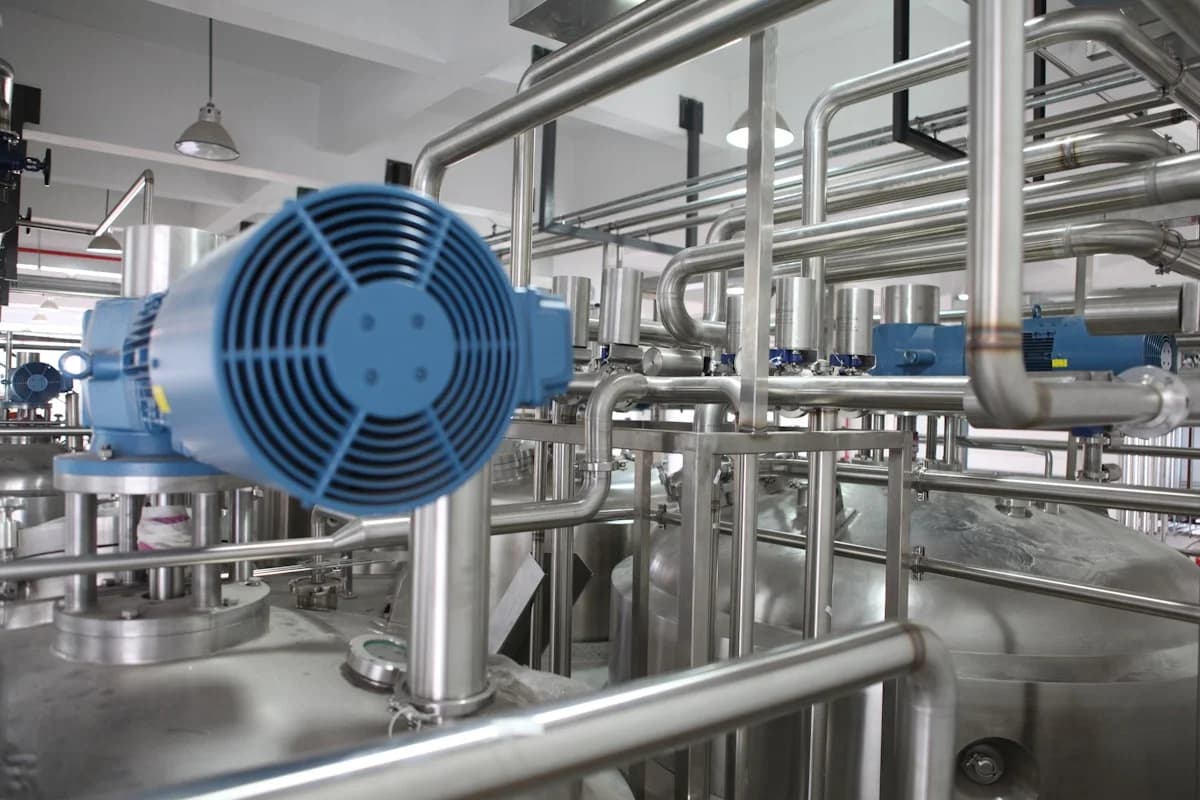
The fluid that ends up in your building
The consequence for fluid selection is a shift in what the secondary coolant is being asked to be.
Where a plant ran on a direct-expansion HFC system, the secondary coolant — if there was one at all — was often a peripheral choice. In an indirect plant built around ammonia or CO2, the secondary coolant is the fluid circulating through the process areas, the cold rooms and the pipework. It is present in far greater volume than the refrigerant charge, and it is the fluid that a maintenance technician actually encounters.
Three questions move up the priority list as a result:
What happens if it leaks? Not primarily a materials question — a safety and clean-up one, in an occupied space.
Is it combustible? This question is often answered from the chemistry name rather than from the documentation, and the two do not always agree. The manufacturer's safety classification places the alcohol-based grades — including the very-low-temperature ones — in the combustible and explosive hazardous materials category, with a flash point of 16 °C for LM-1. The glycol-type grades carry a flash point above 120 °C. The salt-based grades have no flash point and are described as non-combustible. In a loop running through occupied areas that classification is a selection criterion, and it should be confirmed against the current safety data sheet rather than inferred from the fluid's family name.
The concentration each route needs is a separate comparison, and worth having alongside the safety one. At a matched −20 °C freezing point — corresponding to an operating temperature of about −10 °C — calcium chloride brine requires 21 % concentration and is described as severely corrosive, while LM-1 requires 25 % and is described as non-corrosive. The two figures sit close together; the corrosion behaviour does not.
What does it touch? The wetted-material list governs the whole distribution circuit — pipework, coils, valves, seals and every cold-room evaporator — not just a single chiller.
Matching the fluid to the plant
The range offers three broad routes, and the choice follows from the temperature span and the safety case rather than from price:
| Route | Example grade | Flash point / classification | Typical role |
|---|---|---|---|
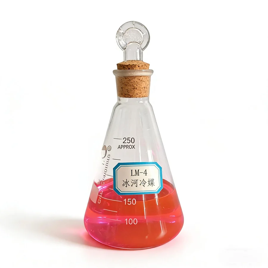
| Glycol-type (modified diols) | LM-4 series | flash point above 120 °C | general industrial circulation across a wide range |
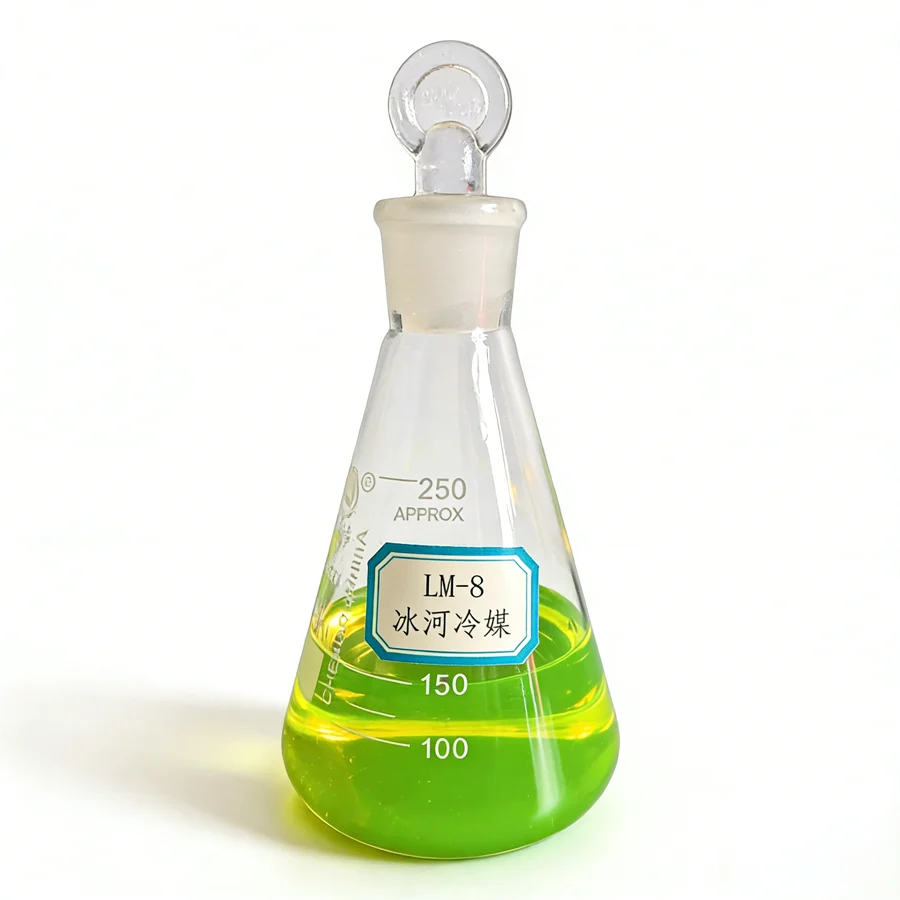
| Salt-based | LM-8 and LM-8A | no flash point — non-combustible | brine duty, and where a non-combustible fluid is required |
| Alcohol-based | LM-1 | combustible — flash point 16 °C | very low temperature, down to −100 °C |
The flammability column is the one tied to occupancy. A fluid with a 16 °C flash point circulating through a production hall is a different proposition from one with no flash point at all, and the route should be chosen against the space classification rather than after it.
The designations for each sit in the low-temperature secondary refrigeration band, and the choice between them is a specification decision — concentration, materials, monitoring — rather than a category preference. Where a site has several duties, it is worth establishing whether one loop with one fluid covers them or whether two loops serve better.
What to check before the plant is designed
Three things belong in the specification from the start, because retrofitting an answer to any of them is expensive:
- The regulatory position that applies to the refrigerant in your jurisdiction and equipment category, including the compliance dates that have already passed and those approaching.
- The full temperature span the secondary loop must cover, including pull-down, defrost and standby conditions.
- The safety case in the occupied areas, which points toward or away from a combustible secondary fluid.
Those three determine which refrigerant is admissible, which secondary coolant routes are open, and how many loops the plant needs. They are worth settling before the mechanical design is frozen — the same sequence set out in the industrial process guide, where the loop architecture and the fluid selection are treated as one decision rather than two.
QUICK CLARIFICATIONS
Common questions.
Is this a ban on HFC refrigerants?
It is a phase-down, not a phase-out. The mechanism caps the total quantity that can be placed on the market and reduces that cap in steps, rather than switching the gases off. The practical effect for a plant is that supply tightens and price rises, which changes the economics of keeping an old system running and the calculus on new plant. Some specific applications also carry direct restrictions with compliance dates — those are the ones to check for your jurisdiction and your equipment category.
Why do natural refrigerants need a secondary loop at all?
Because of where they are safe to use. Ammonia is toxic and CO2 operates at high pressure, so both are best confined to a machinery room with the ventilation, detection and access controls that implies. Flammable refrigerants carry a similar argument. Once the refrigerant is confined, the cooling has to reach the process or the rooms some other way — through a secondary coolant in a separate circuit, exchanging heat with the refrigerant at a chiller or vessel in the plant room.
Does the secondary coolant have to be non-flammable if the refrigerant is flammable?
Not automatically, but the question deserves an explicit answer rather than an assumption. A plant room with a flammable refrigerant already has classified areas and controls; a secondary loop running through a production hall or a cold store has a different risk profile, and the fluid in it is present in far larger volume than the refrigerant charge. A non-combustible secondary coolant removes one hazard from the occupied areas rather than adding to them.
What temperature range does a secondary loop have to cover?
As wide as the site's duties require, which is often wider than a single process. A plant serving cold storage, a process chiller and an air-conditioning load may need a secondary coolant across a considerable span, and one fluid may not cover all of it efficiently. Establishing the full range — including pull-down and defrost conditions, not just operating setpoints — is the first step, and it may point to more than one loop.
CHECK THE SOURCE
References & scope.
- US EPA — technology transitions: HFC restrictions by sector, with GWP limits and compliance dates
- US Federal Register — reconsideration of certain technology transitions requirements, final rule published 26 May 2026
- Star Refrigeration — planning for the F-Gas regulation and HFC phase-down
- Glacier catalogue — LM-4 series models, adaptive metals and temperature ranges (Table 4)
- Glacier catalogue — comparison of secondary refrigerants at a matched freezing point (Section Eight)
Obtain the relevant TDS, SDS and technical approval before use.
How we prepare our content