What flow rate does my loop need?
Sizing a loop needs the cooling load, the fluid's specific heat and the temperature rise you allow. See how they relate, and why fluid choice barely moves it.
THE SHORT ANSWER
What you need to know.
Flow rate follows from three quantities: the cooling load, the fluid's specific heat, and the temperature rise you allow across that load. Divide the load by the other two. The quantity that decides the answer is the permitted temperature rise, not the fluid: among aqueous coolants at a matched freezing point, volumetric heat capacity varies by only about five per cent, so the choice between them barely moves the required volume flow. That spread does not extend to anhydrous or fluorinated fluids, which carry less energy per litre.
- Mass flow is load divided by specific heat and permitted temperature rise. Only one of those three is a property of the fluid.
- Among aqueous coolants compared at a matched freezing point, volumetric heat capacity differs by roughly five per cent, so pipe and pump sizing barely changes with the choice between them.
- Tightening the permitted temperature rise is what increases flow, and pumping power rises faster than flow does.
Three quantities, one of which is yours to choose
Sizing a secondary loop starts from a single relationship, and it is short enough to write out:
flow = load ÷ (specific heat × permitted temperature rise)
The cooling load comes from the process. The specific heat comes from the fluid. The permitted temperature rise is a design decision — and it is the one that moves the answer most.
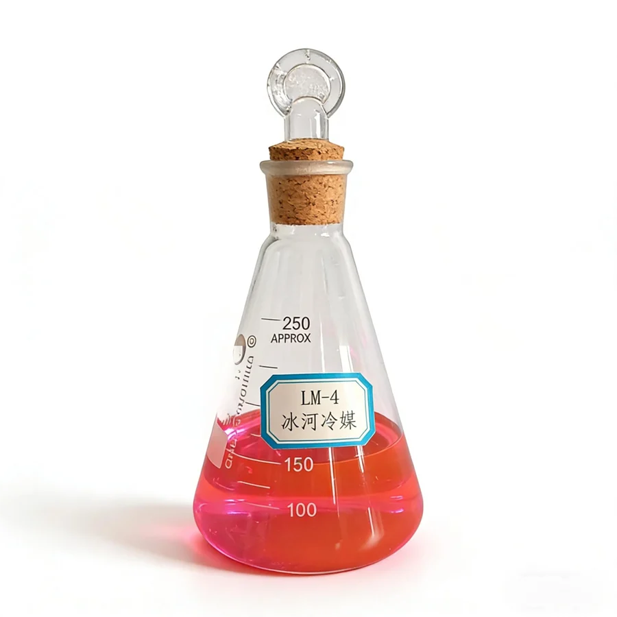
Work it through with real numbers. Take a 100 kW load, and allow the fluid to warm by 5 K across it. For the glycol-type LM-4 at 35 wt%, with a specific heat of 0.837 cal/g·°C — about 3.50 kJ/kg·K — the mass flow is:
100 ÷ (3.50 × 5) = 5.7 kg/s, or about 20.6 tonnes per hour.
That is the whole calculation. Everything else is unit conversion and judgement about the temperature rise.
Why the fluid choice barely moves the answer
The instinct is that specific heat separates the candidates. It does, in mass terms — but not in the terms that size a pump.
Consider five aqueous secondary coolants compared at a matched freezing point of −20 °C, corresponding to an operating temperature around −10 °C. Holding the freezing point constant is what makes the comparison like for like:
| Fluid | Specific heat (cal/g·°C) | Density at 20 °C (g/cm³) | Volumetric heat capacity (cal/cm³·°C) |
|---|---|---|---|
| Calcium chloride brine | 0.721 | 1.20 | 0.865 |
| Ethylene glycol | 0.825 | 1.05 | 0.866 |
| Alcohol | 0.90 | 0.97 | 0.873 |
| LM-1 (alcohol-based) | 0.950 | 0.96 | 0.912 |
| LM-4 (glycol-type) | 0.837 | 1.05 | 0.879 |
Read the specific heat column alone and there is a spread of about 32 per cent between the lowest and the highest. That looks like a real differentiator.
Now read the last column, which multiplies specific heat by density. The spread collapses to about five per cent.
The reason is that density compensates. The fluids with the highest specific heat are also the lightest, so a litre of each carries a similar amount of energy per degree. And it is litres per second — not kilograms per second — that set pipe velocity, pressure drop and pump duty.
So for a given load and a given permitted temperature rise, all five fluids demand very nearly the same volume flow. Fluid selection barely touches loop sizing.
What actually changes the flow
If the fluid does not move the answer, the permitted temperature rise does — and it does so linearly.
Halve the permitted rise from 5 K to 2.5 K and the flow doubles. That has consequences that go well beyond a larger pump: pressure drop through fixed pipework rises roughly with the square of flow, and pumping power roughly with the cube. A small tightening of the temperature-rise target can multiply the energy bill for circulation.
This is the same mechanism that makes viscosity matter more than specific heat at low temperature, set out in pumping energy, not heat capacity, decides a low-temperature coolant. Specific heat tells you how much fluid you need; viscosity and flow tell you what it costs to move.
There is a second reason to allow the widest temperature rise the process tolerates. A larger rise across the load means a smaller rise is needed elsewhere in the circuit, which can reduce the flow a chiller or heat exchanger has to handle — sometimes allowing a smaller unit.
The unit trap that ruins the comparison
Specific heat is printed in two conventions, and they are not close in magnitude.
The figures above are in cal/g·°C. Many datasheets now use kJ/kg·K instead, and one cal/g·°C is about 4.184 kJ/kg·K. So LM-4 at 0.837 cal/g·°C is roughly 3.50 kJ/kg·K — a number that looks four times larger for the same fluid.
Compare the two conventions without converting and the error is a factor of about four, in whichever direction you are reading. This is covered in more detail, along with the other unit traps, in how to read a coolant datasheet.
The same discipline applies to the flow side: mass flow and volume flow need density to convert between them, and density at the operating temperature — not the 20 °C stock figure — is the one that matters.
What to assemble before the calculation
Four inputs, and three of them come from your process rather than from a supplier:
- The cooling load, in kW, at the condition that governs — usually the design maximum, not the average.
- The permitted temperature rise across the load, and whether it is set by the process, the equipment or a convention.
- The fluid's specific heat and density at the operating concentration and temperature. Both move with concentration, so the figures for 20 wt% do not describe a loop running at 50 wt% — see how much glycol to add.
- The acceptable velocity in the pipework, which turns the volume flow into a diameter. This is a design choice rather than a fluid property, and it is usually taken from a band rather than a single figure:
| Line | Common design band | What sets the ceiling |
|---|---|---|
| Pump suction | 1–2 m/s | cavitation margin at the pump inlet |
| Discharge and mains | 2–3 m/s | pressure drop traded against pipe cost |
| Branches and terminal connections | 1.5–3 m/s | noise, erosion and vibration |
Those bands are ordinary practice for pumped water-based coolants in steel pipework. The figure that applies to a specific loop depends on the fluid, the pipe material, the acceptable pressure drop and the acoustic environment — which is why velocity belongs in the specification rather than being assumed. At 35 m³/h, a 2 m/s limit points to DN 80 rather than DN 65.
Get those four and the loop sizes itself. The remaining work is confirming that the fluid you selected can actually be pumped at the temperature you intend — which is a viscosity question, not a specific-heat one.
The system curve decides the rest
The relationship above gives a design flow rate. It does not give you a pump, a pipe diameter or a pressure drop, and none of those can be settled from a specific-heat figure.
Pump selection depends on the system curve — pipe lengths, fittings, heat-exchanger pressure drop, elevation — at the coldest condition the loop will see, where viscosity is highest. Pipe sizing depends on an acceptable velocity that balances capital cost against pumping energy. Both are engineering decisions for the loop as built, with the actual fittings and the actual heat exchangers in place.
Bring the four inputs, the loop volume and a system diagram to your supplier or designer. What you are asking for is a pump duty point and a pipe schedule, and those are answered against the installation rather than the fluid.
QUICK CLARIFICATIONS
Common questions.
Can I work the flow rate out from the pipe size instead?
No — that reverses the calculation. Pipe diameter sets the velocity for a given volume flow, and velocity sets pressure drop and pumping power. Flow comes first, from the load and the permitted temperature rise; the pipe is then sized to carry it at an acceptable velocity. Sizing pipe first and asking what load it can serve produces a loop that either runs too fast or wastes material.
Why does a smaller temperature rise need more flow?
Because the same heat has to be carried away by a smaller temperature change, so more mass has to pass per second. Halving the permitted temperature rise doubles the required flow. Pumping power rises faster than flow — roughly with the cube of flow through fixed pipework — which is why an aggressive temperature-rise target is often the most expensive decision in a secondary loop.
Is mass flow or volume flow the one that matters?
Both, for different purposes. Mass flow and specific heat set the heat carried; volume flow sets pipe velocity, pressure drop and pump duty. Because density varies between fluids, the two do not track each other. Converting between them needs the density at the operating temperature, not at 20 °C.
Does a higher specific heat mean I can use a smaller pump?
Not by much, and not on its own. A fluid with higher specific heat carries more energy per kilogram, so the mass flow falls. But pump duty follows volume flow, and a denser fluid needs fewer litres per second for the same mass. The two effects partly cancel: across common secondary coolants the required volume flow varies by only a few per cent.
CHECK THE SOURCE
References & scope.
- Glacier catalogue — specific heat, density and thermal conductivity of five secondary refrigerants at a matched freezing point (Section Eight)
- Glacier catalogue — LM-4 series concentration, density, freezing point and viscosity (Table 3)
- Glacier catalogue — LM-1 series physical parameters (Table 1)
Obtain the relevant TDS, SDS and technical approval before use.
How we prepare our content