800 V DC: what the higher voltage changes for the cooling loop
Moving rack power to 800 V DC changes more than the busbar. See why a higher system voltage tightens the fluid's conductivity requirement, and by how much.
THE SHORT ANSWER
What you need to know.
Rack power is moving from alternating current to 800 V direct current, because at megawatt rack densities the copper and the conversion losses of a lower-voltage distribution become the constraint. For the cooling loop, the change is not the voltage itself but what follows from it. A fluid beside a live conductor passes a leakage current proportional to voltage times conductivity, so for a fixed acceptable leakage the allowable conductivity falls as voltage rises. Moving from 400 to 800 V halves it. That is a requirement on the fluid, set by an electrical decision.
- The conductivity limit beside live conductors has two drivers: galvanic corrosion, which is largely voltage-independent, and leakage current, which scales with voltage.
- At a fixed acceptable leakage current the allowable conductivity is inversely proportional to system voltage.
- More of the rack becomes liquid-cooled at 800 V, so the loop captures heat from power components as well as processors.
1. Why rack power is changing
For most of the history of the data centre, power reached the rack as alternating current at a few hundred volts and was converted down through several stages inside the rack. That worked while a rack drew ten kilowatts. It stops working when a rack draws a megawatt.
Two things become prohibitive at high density, and for different reasons. Copper has to carry the current, and the cross-section needed grows with the current — this one is directly current-driven. Conversion happens at every stage from the supply to the processor rail, and each stage loses a few per cent of the power passing through it, so the cost scales with the number of stages rather than with the current.
Raising the voltage for the same power lowers the current proportionally, which cuts the copper. It also allows the power chain to be restructured so that fewer conversion stages are needed, which is where most of the efficiency gain comes from. 800 V direct current is the architecture the industry is converging on: fewer stages, lower losses, and a substantial reduction in conductor cross-section. The transition is by solid-state transformer or transformer rectifier unit, and it is being driven from the highest-density racks downward. As of September 2026 it is in pilot and early deployment at the top of the density range, with wider adoption expected from 2027.
For the cooling engineer, the interesting part is not the voltage. It is the two things that follow from it.
2. What follows: more of the rack goes into the loop
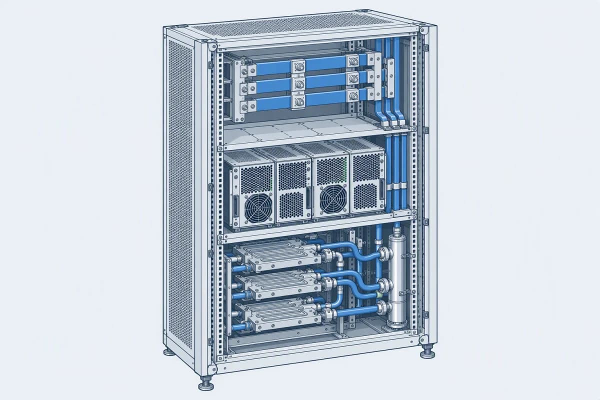
The first consequence is thermal. At these densities the power delivery components are no longer incidental heat sources. Busbars, power shelves and the converters that step 800 V down to the processor rail all dissipate, and the pressure on power density pushes them toward liquid cooling as well.
The practical effect is that the loop captures more heat for the same compute. Components that were previously air-cooled — and therefore contributed nothing to the liquid loop's duty — now sit in the liquid path. Loop sizing done on processor power alone will be short.
The second consequence is electrical, and it is the subject of the next section.
3. The conductivity requirement tightens with voltage
A fluid sitting beside a live conductor is not a perfect insulator. It passes a small leakage current, and the magnitude of that current is set by Ohm's law applied to the fluid path:
I = V / R, where R is the resistance of the fluid path
The resistance of that path depends on the fluid's conductivity, σ, the length of the path, L, and its cross-sectional area, A:
R = L / (σ · A)
Substituting, the leakage current is:
I = V · σ · A / L
For a given installation, A and L are fixed by the geometry of the leak path. So for a fluid of a given conductivity, the leakage current is proportional to the voltage across that path. Double that voltage and you double the leakage current — or, to hold the leakage current at the same acceptable value, you must halve the conductivity.
| System voltage | Conductivity the same leakage current allows |
|---|---|
| 400 V | σ |
| 800 V | σ / 2 |
That relationship is worth stating plainly, because it is easy to miss: one of the limits on a fluid's conductivity is set not by its chemistry but by the voltage of the hardware beside it. It is one limit among several, and the physics above does not by itself tell you what number to specify — see the qualifications that follow and section 6.
Two qualifications are needed before the factor of two is used for anything.
The relevant voltage is the voltage across the leak path, not the nameplate voltage of the architecture. The published 800 V proposals are not all the same circuit. A bipolar ±400 V arrangement carries a grounded midpoint, so a path from either rail to chassis sees 400 V, not 800 V. A monopolar 800 V arrangement relies on floating operation with insulation monitoring, or on a solidly grounded return, and the voltage a given path sees depends on which. Whether the conductivity requirement actually tightens — and by how much — depends on the topology, and that is a question for the electrical designer rather than for the fluid supplier.
The geometry is not constant between generations. Creepage distance is required to grow with voltage, which lengthens the leak path and works against the effect above, while more components entering the liquid loop increases the wetted area and works with it. The factor of two describes a fixed geometry; a real transition changes several things at once.
The second driver, which does not move
Conductivity is limited for more than one reason, and only one of them scales with voltage.
Galvanic corrosion is an electrochemical process driven by the potential difference between dissimilar metals in contact with the fluid. Its rate depends on the fluid's ionic content and on which metals are present; it does not become more severe because the rack power supply runs at a higher voltage.
Leakage current is the mechanism above, and it scales directly with voltage.
A third driver has nothing to do with either. Conductivity is also used as an indicator of the loop's health: inhibitor depletion, metal dissolution and ions carried in by make-up water all raise it. That is why conductivity is monitored for trend rather than set once, and why a rising reading is acted on even when the absolute value is unremarkable.
A fourth mechanism is voltage-driven but is not a leakage current at all. Electrochemical migration is the dissolution of metal at an anodic site, transport of the ions through a thin film of moisture, and re-deposition as a conductive dendrite at the cathode. It needs four conditions together: a potential difference, moisture, a metal that can migrate, and ionic contamination on the surface. It is not governed by the ohmic leakage current but by the electric field across the gap, and it is non-linear in voltage — a published study of surface-mount resistors finds no dendrite growth at 2 V and complete, short-circuiting dendrites at 3 to 4 V. The relevance to a high-voltage rack is that the field across a narrow gap is what drives it, and the field is set by the voltage rather than by the fluid's conductivity. Conformal coating, cleanliness and moisture control are its countermeasures, not the conductivity specification.
None of that makes the conductivity requirement unimportant — it makes it one of several electrical requirements rather than the only one.
And none of these limits is published as a derivation. The conductivity figures that appear in equipment specifications and operator guidance are absolute numbers set by the equipment manufacturer, not values calculated from an acceptable leakage current. The relationship above explains why voltage matters to the requirement; it does not reproduce the number in the specification. Where a fixed current threshold does exist in practice, it sits in the protection layer — insulation monitoring and earth-fault detection — not in the fluid chemistry.

4. What the standards cover
Guidance for modular thermal control systems sets numerical limits on several fluid parameters, and it is worth being precise about which are which:
| Parameter | Guidance |
|---|---|
| pH | 7.0 to 9.0 |
| Particulate | ≤ 25 µm at turnover, ≤ 10 µm in steady operation |
| Dissolved gas | below 1 % by volume |
| Inhibitor concentration | within ±10 % of the manufacturer's target |
Conductivity is treated differently, and the difference matters. In that guidance it appears as a parameter to monitor continuously rather than as a limit with a number attached. The numerical conductivity limits that operators actually work to come from the equipment side — the cold plate and CDU specifications issued by the hardware vendor — and they are given as absolute values at a stated temperature, not derived from a leakage-current allowance. That is the practical consequence of section 3: the mechanism ties conductivity to voltage, but the number in your specification comes from the equipment manufacturer, and it should be taken from there rather than calculated.
Three observations follow from that table.
First, the four tabulated limits are as binding as the conductivity figure. A fluid that meets a conductivity target and misses the inhibitor or particulate ones is not a compliant loop, and the particulate limits in particular are tighter than most process cooling would ever need — because cold plate channels are narrow.
Second, the conductivity figure is a limit on the loop, not a rating of the concentrate. It is measured in service, at a stated temperature, on the diluted fluid — and the dilution raises it. A fluid whose concentrate is quoted below 1 µS/cm — the LM-4D grade is an example — is specified at below 5 µS/cm at 50 % dilution in the same document, an order of magnitude higher. The gap is not simply the water: both figures come from the same document, which specifies ultrapure water for the dilution. What it shows is that the in-service figure is not the concentrate figure, and that make-up water can dominate the reading over time — which is why its specification carries as much weight as the fluid's own figure.
5. What to specify
Four items, and the first two are decided before the fluid is chosen:
- The system voltage, from the hardware roadmap rather than the current installation. A loop specified today will probably meet 800 V at its next hardware refresh.
- The conductivity limit the equipment vendor applies, together with the voltage a leak path would actually see. Where a vendor states an acceptable leakage current, the relation above shows how the limit moves with voltage; where they do not — which is common — their absolute conductivity figure is the binding number and the relationship is context rather than an input.
- The conductivity of the fluid as it will actually run, at operating dilution and on the site's make-up water — not the concentrate figure.
- The dilution water specification, which sets the floor the loop can reach regardless of which concentrate is used.
6. Limitations
The leakage relationship is a scaling law, not a standard. The derivation shows how the allowable conductivity moves with voltage for a fixed leak-path geometry. Real installations have several paths of different lengths and areas, and standards set absolute figures rather than deriving them per site. The relationship is the reason the requirement tightens; the number still comes from the vendor and the applicable guidance.
A leak path is assumed, not predicted. Whether a loop ever experiences the leakage current the derivation bounds depends on whether fluid contacts a conductor at all. A well-built loop never does. The requirement exists because the consequence of being wrong is severe, not because leakage is expected in normal operation.
The guidance quoted is for general modular thermal systems, not for 800 V specifically — and it is current as of September 2026. Numerical conductivity limits for 800 V distribution are still being settled alongside the hardware, which is the main reason this section is a set of qualifications rather than a table of numbers.
Conductivity figures are temperature-dependent. A limit stated at 25 °C is not the value a loop will show at 45 °C, and conductivity rises with temperature. Monitoring has to record the temperature alongside the reading for the trend to mean anything.
No independent measurement was made. Product figures are reference values published by the manufacturer, and no independent testing or third-party endorsement is implied.
7. Where the requirement actually lands
The electrical architecture is decided by the compute roadmap, and the cooling loop inherits a conductivity requirement from it. That is the real content of the 800 V transition for a thermal engineer: not a new fluid, but a tighter bound on the same fluid, arriving from a decision made in a different discipline.
The practical implication is that a loop designed with margin on conductivity will absorb the transition, and one designed to the current limit exactly will not. Given that the hardware refresh cycle is shorter than the life of the pipework, specifying the tighter bound now moves the cost to the design stage rather than to a retrofit — and a design-stage decision is the cheaper place to make it.
Bring the system voltage, the vendor's acceptable leakage current and the site's water analysis to your supplier. What you are asking for is a conductivity target for the loop as built, which is answerable from those three inputs rather than from a general figure.
QUICK CLARIFICATIONS
Common questions.
Why does a higher voltage need a lower-conductivity fluid?
Because leakage current through the fluid is voltage divided by the fluid's resistance, and that resistance falls as conductivity rises. For a path of fixed geometry the current is proportional to voltage times conductivity. Hold the acceptable leakage current fixed and the allowable conductivity becomes inversely proportional to voltage: doubling the system voltage halves the concentration of dissolved ions the fluid may carry. Galvanic corrosion sets a separate limit that barely moves with voltage, so the requirement a fluid has to meet is whichever of the two is tighter.
Does a lower conductivity always mean a better fluid for an 800 V loop?
No. Conductivity is one requirement among several, and the ultra-low grades that reach the lowest figures do so by changing the additive package — often by removing the inorganic salts that carry the ionic load. That can change what the fluid is compatible with and how it must be diluted. A grade quoted below 1 µS/cm in the concentrate is specified at below 5 µS/cm at 50 % dilution in the same document, so the in-service figure is not the concentrate figure — and make-up water can dominate it over time, which is why the water specification matters as much as the concentrate figure.
What else changes when the rack runs at 800 V DC?
More of the rack becomes liquid-cooled rather than air-cooled. At these densities the power delivery components — busbars, power shelves, and the converters that step voltage down to the processor rail — are themselves significant heat sources, and pressure on power density pushes them into the liquid path. That raises the heat the loop has to carry for the same compute, and it puts fluid next to components that were previously air-cooled. Both changes belong in the loop sizing and in the material compatibility list.
Is 800 V DC in service now, or still a plan?
It is in pilot and early deployment for the highest-density racks, with the industry position that designers should now plan for it. The published timelines point to wider adoption from 2027. That is early enough that a facility being specified today will probably meet it, which is an argument for making the loop capable of the tighter conductivity requirement rather than discovering it at the next hardware refresh.
CHECK THE SOURCE
References & scope.
- Glacier catalogue — LM-4D ultra-low-conductivity grade, composition and conductivity at 20 °C (printed page 13)
- Glacier catalogue — LM-4D conductivity and pH interval, ultrapure dilution (printed page 14)
- Schneider Electric — 800 VDC data centre cooling: implications, infrastructure evolution and operational impact
- ASHRAE — AI data centre framework: integrated design principles, including the 800 VDC rack pilot
- NVIDIA — 800 V HVDC architecture for next-generation AI factories, including the 2027 production timeline
- Journal of Electronic Materials — effect of bias voltage on electrochemical migration failure of surface-mount resistors
- Open Compute Project — CDU performance and specification guidance for modular thermal control systems
Obtain the relevant TDS, SDS and technical approval before use.
How we prepare our content